Universal JTAG User Manual (Parallel)

10 PCS, 10cm x 10cm, 2 layers prototype for $38.80 shipped!
Buy various JTAG cables for your Satellite Receiver, Cable Modem, Wireless Router, Standard Wiggler from http://www.easymg.com and http://www.diygadget.com
Contents
- 1 Why you need an universal JTAG adapter?
- 2 What is our universal JTAG adapter?
- 3 Board layout
- 4 Buffered or unbuffered
- 5 Configure it to use with TJTAG for wireless routers
- 6 Configure it to use with Blackcat software for your cable modem (Motorola, Webstar etc.)
- 7 Configure it for XBOX 360, so you can mod your 360 to play xbox 360 homebrew emulators
Why you need an universal JTAG adapter?
There are many different JTAG cables available in the market, often they are not compatible to each other. The problem was cause by the software. JTAG standard only defines a few hardware pinouts. However there is no standard definition on the PC side, e.g. which DB25 pin is for TDI? This is really depending on the software, some JTAG softwares may assume TDI is connected to pin 2 of DB25, but others may assume it is on pin 3. Even for the JTAG connector side, there are many different pinouts, 20 pin JTAG, 14 PIN, 12 PIN, 10 PIN etc... in a nutshell, you need a JTAG cable/adapter is flexible enough to allow you configure it for different softwares/programmers so you only need to invest on one JTAG adapter.
You need a PC with parallel port. USB to parallel adapter will NOT work.
No USB port? no problem, use our USB JTAG:
TIAO Multiple Protocol Adapter (JTAG/SPI/I2C/Serial)
Tutorial (debrick router using USB):
Debrick Wireless Router Using TUMPA and zJTAG
What is our universal JTAG adapter?
Our parallel universal JTAG adapter allows you to easily configure it to be a buffered or unbuffered JTAG. With provided flexible jumper wire you can move the pin configuration easily to suit different programmers.
Board layout
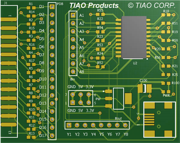
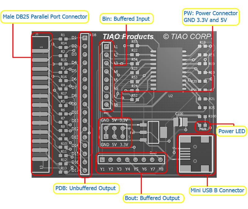
PW is the power output. Remember this board utilizes the USB power, which by default only provides 100mA at 5V. If you connect the power header to a component requires more current, it will damage your USB port.
PW provides two GND, two 5.0V and two 3.3V outputs.
PWR is a power on LED. When USB cable is connected, the LED will light. If you want to use it in unbuffered mode, you do not need to connect the USB cable.
PDB is the header which directly connected to DB25's pin from 1 to 17 via a 100 Ohm resistor. E.g header D1 is connected to Pin 1 of parallel port via 100 Ohm resistor, header D9 is connected to Pin 9 of parallel port via 100 Ohm resistor, etc.
Bin is the buffer input header. We use 74HCT244 as the buffer chip. Bout is buffer output header.
Y1 is the buffered output of A1 Y2 is the buffered output of A2 and so on...
Buffered or unbuffered
The product comes with 6 x 50cm color coded flexible cable and 6 x 10cm color coded flexible cable.
If you want to use the adapter in unbuffered mode, you only use the 6 x 50cm flexible cables. Do not connect USB cable to your PC in this case.
If you want to use the adapter in buffered mode, you need all the cables plus you need to connect the adapter to your PC's USB port via a USB A to Mini USB B cable. Once the USB cable is connected, the PWR LED will light.
Configure it to use with TJTAG for wireless routers
In the following example, I am using Linksys WRTG54 wireless router as one example.
| DB25 | Router | Function |
|---|---|---|
| 2 | 3 | TDI |
| 3 | 9 | TCK |
| 4 | 7 | TMS |
| 5 | 1 | TRST (Not Connected) |
| 13 | 5 | TDO |
| 18-25 | 2,4,6,8,10 | GND |
Since TRST is not used, you only need 5 flexible cables.
Unbuffered mode
You just need 5x50cm flexible cable connected in such way:
Insert one end of the red flexible cable to D2, and the other end to your router's TDI, in this case is PIN 3.
Insert one end of the yellow flexible cable to D3, and the other end to your router's TCK, in this case is PIN 9.
Insert one end of the green flexible cable to D4, and the other end to your router's TMS, in this case is PIN 7.
Insert one end of the blue flexible cable to D13, and the other end to your router's TDO, in this case is PIN 5.
Insert one end of the black flexible cable to GND, and the other end to your router's GND, in this case is 2, 4, 6, 8 or 10.
Once connected, connect the adapter to your PC's parallel port, then you are all set.
You can follow the following instructions to debrick your router:
Buffered mode
In buffered mode, you will need 5-7 pieces 10 cm flexible cable and 5-8 pieces of 50 cm flexible cable (again, they come with the package).
On board configuration:
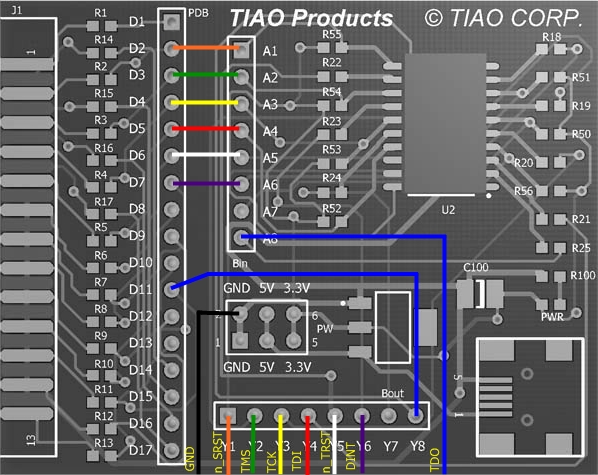
Insert one end of the 10cm orange flexible cable to D2, and the other end to A1 -> this is optional, if pin "n_SRST" is not active, do not connect it.
Insert one end of the 10cm green flexible cable to D3, and the other end to A2
Insert one end of the 10cm yellow flexible cable to D4, and the other end to A3
Insert one end of the 10cm red flexible cable to D5, and the other end to A4
Insert one end of the 10cm white flexible cable to D6, and the other end to A5
Insert one end of the 10cm purple flexible cable to D7, and the other end to A6 -> this is optional.  If pin "DINT" is not active, do not connect it.
Insert one end of the 10cm blue flexible cable to D11, and the other end to Y8
Connect to your router:
Insert one end of the 50cm orange flexible cableto Y1, and the other endto the routers n_SRST pin, in this case pin 11 -> this is optional, if pin "n_SRST" is not active, do not connect it.
Insert one end of the 50cm green flexible cable to Y2, and the other end to your router's TMS pin, in this case is PIN 7.
Insert one end of the 50cm yellow flexible cable to Y3, and the other end to your router's TCK pin, in this case is PIN 9.
Insert one end of the 50cm red flexible cable to Y4, and the other end to your router's TDI pin, in this case is PIN 3.
Insert one end of the 50cm blue flexible cable to A8, and the other end to your router's TDO pin, in this case is PIN 5.
Insert one end of the 50cm black flexible cable to GND, and the other end to your router's GND pin, in this case is 2, 4, 6, 8 or 10.
Insert one end of the 50cm white flexible cable to Y5, and the other end to your router's n_TRST pin, in this case is PIN 1.
Insert one end of the 50cm purple flexible cable to Y6, and the other end to the routers DINT pin, in this case pin 13 -> this is optional.  If pin "DINT" is not active, do not connect it.
Connect the JTAG board to your PC:
Connect the board to the parallel port of your PC
Connect the board to your pc's USB port via a USB cable
You are all set.
You can following the following instructions to debrick your router:
Configure it to use with Blackcat software for your cable modem (Motorola, Webstar etc.)
You can connect your cable modem and your pc via JTAG cable to do some interesting test, such as change MAC address, serial number, bootloader and firmware.
Unbuffered mode
In this mode, the JTAG adapter is configured to be acting as a unbuffered JTAG, thus you do NOT need to power it using USB cable.
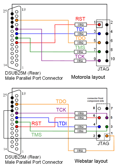
This is a schematic of the unbuffered Surfboard and Webstar JTAG cable:
From above schematic, you can figure out that there are six (6) connections (RST, TDI, TDO, TMS, TCK and GND).
You also notice that Motorola's JTAG header is different than the Webstar. Motorola has a 10 pin header and Webstar has a 8 pin header. However, with our Universal JTAG, this don't matter because you can use the flex cable.
Here is how to configure our Universal JTAG Adapter to work with cable modems:
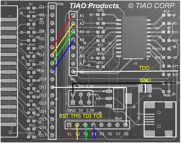
Insert one end of the red flexible cable to D6, and the other end to your modem's RST, (Motorola: PIN 1, Webstar: PIN 6)
Insert one end of the yellow flexible cable to D7, and the other end to your router's TMS, (Motorola: PIN 7, Webstar: PIN 3)
Insert one end of the green flexible cable to D8, and the other end to your router's TDI, (Motorola: PIN 3, Webstar: PIN 4)
Insert one end of the blue flexible cable to D9, and the other end to your router's TCK, (Motorola: PIN 9, Webstar: PIN 5)
Insert one end of the white flexible cable to D11, and the other end to your router's TDO, (Motorola: PIN 5, Webstar: PIN 1)
Insert one end of the black flexible cable to GND, and the other end to your router's GND, (Motorola: PIN 2, 4, 6, 8, 10, Webstar: PIN 2 or 7)
Bingo! you are all set.
Now connect your universal JTAG adapter to your PC's parallel port, turn on the modem, launch the blackcat software and have fun modding it!
Buffered mode
In this mode, the JTAG adapter is configured to be acting as a buffered JTAG, thus you need to power it using USB cable (USB A to Mini USB B, comes with most digital camera).
Use the unbuffered schematic above as the reference, we need 6 connects plus an USB cable.
On board configuration:
Insert one end of the 10cm red flexible cable to D6, and the other end to A1
Insert one end of the 10cm yellow flexible cable to D7, and the other end A2
Insert one end of the 10cm green flexible cable to D8, and the other end to A3
Insert one end of the 10cm blue flexible cable to D9, and the other end to A4
Insert one end of the 10cm white flexible cable to D11, and the other end to Y8
Connect to your router:
Insert one end of the 50cm red flexible cable to Y1, and the other end to your modem's RST, (Motorola: PIN 1, Webstar: PIN 6)
Insert one end of the 50cm yellow flexible cable to Y2, and the other end to your router's TMS, (Motorola: PIN 7, Webstar: PIN 3)
Insert one end of the 50cm green flexible cable to Y3, and the other end to your router's TDI, (Motorola: PIN 3, Webstar: PIN 4)
Insert one end of the 50cm blue flexible cable to Y4, and the other end to your router's TCK, (Motorola: PIN 9, Webstar: PIN 5)
Insert one end of the 50cm white flexible cable to A1, and the other end to your router's TDO, (Motorola: PIN 5, Webstar: PIN 1)
Insert one end of the 50cm black flexible cable to GND, and the other end to your router's GND, (Motorola: PIN 2, 4, 6, 8, 10, Webstar: PIN 2 or 7)
Connect the JTAG board to your PC:
Connect the board to the parallel port of your PC
Connect the board to your pc's USB port via a USB A to mini USB B cable (comes with most digital camera)
You are done. Power your modem and run the application to finish your testing work!
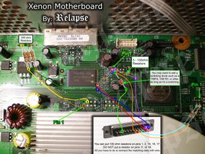
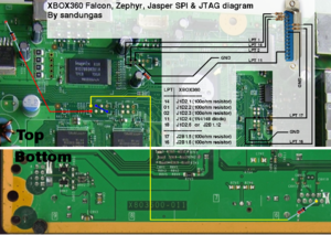
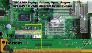
Configure it for XBOX 360, so you can mod your 360 to play xbox 360 homebrew emulators
Please do not attempt this if you are not a advanced modder.
IMPORTANT
After peforming this hack the xbox 360 can only run homebrew not xbox games or dash unless you install a cynos chip, run the mod f/w on cynos chip and std f/w on the onboard nand chip or vise verser and switch between the 2 depending on what you want to run. If you do update with the latest xboxlive update homebrew will never run on that xbox again even if the update is done after the mod.
Unbuffered mode
We do not recommend run it in unbuffered mode. Parallel port provides +5V, your xbox 360 needs +3.3V, so it could damage your parallel port or xbox 360.
Buffered mode
References:
JTAG Xenon Tutorial for Xbox Emulators
Buy various JTAG cables for your Satellite Receiver, Cable Modem, Wireless Router, Standard Wiggler from http://www.easymg.com and http://www.diygadget.com

10 PCS, 10cm x 10cm, 2 layers prototype for $38.80 shipped!

