How to JTAG XBOX 360

10 PCS, 10cm x 10cm, 2 layers prototype for $38.80 shipped!
Contents
Buy Game Console Adapters from http://www.easymg.com or http://www.diygadget.com
Why you want to JTAG your XBOX 360?
If you want to run homebrew... simple enough!
In this tutorial I am going to show you how to modify your XBOX 360 to run Xell Homebrew or xbox rebooter kernel.
Tools needed
In order to finish this task, you need to prepare the following tools/components:
- A ‘hackable’ XBOX 360
- Buffered XBOX 360 JTAG bundle (buy it from here)
- Solder iron, solder and solder paste.
Software needed:
- NANDPro ( current Version 2.0 d)
- Infectus NAND Checker (currently Version 1.1)
- MD5 Comparison Tool (hex editors can do this)
- 360 Flash Tool ( currently Version 0.91)
- CD Info (currently Version 1b)
The benefit of using this buffered jtag board is, the data is buffered so it is much reliable then the unbuffered one. The parallel port is TTL data, which is 5V, but your NAND uses 3.3v, so a homemade unbuffered cable could damage your NAND. This buffered JTAG board is a native 3.3v device, so it is much safer.
OK, let’s start!
How do I know my XBOX 360 is hackable?
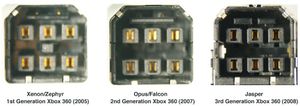
This is relatively easy, check the power connector:
Differences between Xenon/Zephyr: Zephyr has HDMI, Xenon does not.
Difference between Falcon/Opus: Falcon has HDMI, Opus does not.
If you have a Jasper box, you should also check which NAND size it has.
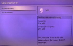
Unplug all storage devices (HDD, Memory Unit etc.) and navigate to "System Settings", "Memory". If you don't see a storage device listed there you have a Jasper without an integrated Memory Unit, so you have a 16MB NAND. If a storage device is listed (with a symbol of an Xbox console in front) press the Y-Button and a summary from the storage device will appear.
Identification:
Capacity: 214MB = 256MB NAND
Capacity: 451MB = 512MB
Which Dashboard-Version does my console have?
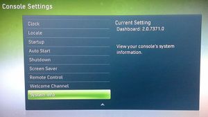
At first you have to find out which dashboard version your Xbox console has. Go to "System Settings", "Console Settings" and choose "System Info". The dashboard should show something like "2.0.7371.0".
It is possible to use the hack up to Version 7371, but starting with Dashboard-Version 8xxx it isn't possible anymore.
With Jasper, beginning MFR July 2009, you have to read out the NAND first anyway to know for sure that the Hack will work. (The NAND should be read out anyway, doesn't matter which Mainboard-Revision you have).
Preparation
You first need to disassemble your XBOX 360, there are tons of instructions on the internet, so I am not going to cover it here.
We need to prepare the wires which will be soldered on to your XBOX 360 motherboard.
Open the buffered JTAG bundle, you will see a PCB board with chips on it, this is the JTAG board. You will also see a few female to female jumper wires, put them aside, we will use them later on. We will be soldering the grey flat cable on your mother board, so let’s prepare them.
The supplied flat cable is 4-conductor and 50cm in length. Use a scissor or utility knife to cut it in half (25 cm x 2). So we now have 8 pieces of wires, and each has 25cm in length. We need to solder 7 wires to the mother board. Strip one wire off the flat cable, now you have a bundle of 4 wires, a bundle of 3 wires and one alone.
First, strip the insulation like this, and dip some solder paste on each wire:
Then apply some solder on it, so it will be must easier to solder the wires later on.
Repeat this step to all wires.
Now cut 7 pieces of the heat shrink tube (2.5-3cm long each), and use pliers to strip 7 pin headers from the 40-pin IDC header, insert the wires to one heat shrink tube, then solder the pin header on the wire:
Repeat this step to all 7 wires. These are the sides will be connected to the JTAG board. The other side of the wires will be directly soldered to the mother board, so don’t solder the header on the other end of the wires. Then move the heat shrink tube to cover the solder point and use the outside of the solder iron to give some heat to the shrink tube. The tube will shrink and they look like:
The other end will be soldered to the mother board, so we need to prepare them as well. Strip 1.5mm insulation off. Dip some solder paste and give some solders on it so it will be easier to solder them later on:
If you want to leave the JTAG cable soldered on the mother board after you have read/write the flash, you need to do the following, otherwise you can skip next step.
Insert both cables through the bottom hole on the case. This is what it looks like:
Solder the JTAG Wires
Now, let see where we need to solder the wires:
In the above picture, I have 2 red circles. There are the POI. We need to solder wires on 1,2,3,4,6 in the top circle and 5,6 in to the bottom circle.
Before we solder the wires on them, use a q-tip to apply some solder paste on these pads, and then use your solder iron to apply little bit solder on these pads.
Since you have 2 flat cables, one is 4-conductor and another one is 3-conductor, it is good idea to make a mark on the pin 1 of each flat cable so you won’t mess them up later on.
This is what I did:
Use a marker so something to identify pin 1 on each flat cable, then use the following configure to solder the wires:
Point on map			Pin number

Top circle 1			pin 1 of 4 conductor cable
Top circle 2			pin 2 of 4 conductor cable
Top circle 3			pin 3 of 4 conductor cable
Top circle 4			pin 4 of 4 conductor cable
Top circle 6			pin 1 of 3 conductor cable
Bottom circle 5			pin 2 of 3 conductor cable
Bottom circle 6			pin 3 of 3 conductor cable
I started with point 6 in the top circle:
Then solder the other wires:
And the bottom circle (sorry forgot to take a picture)
Prepare the JTAG connection
Now insert the 50 cm long female wires to the headers as shown in the photo:
Red        wire 1      J1D2 Pin 1 (top circle)
Blue       wire 2      J1D2 Pin 2 (top circle)
Orange     wire 3      J1D2 Pin 3 (top circle)
Yellow     wire 4      J1D2 Pin 4 (top circle)
Black      wire 5      J1D2 Pin 6 (top circle)
White      wire 6      J2B1 Pin 5 (bottom circle)
Green      wire 7      J2B1 Pin 6 (bottom circle)
Now on the JTAG board, connect the 10cm female to female wires as below:
Blue		D1 to A1
Orange		D2 to A2
Red		D14 to A4
Green		D16 to A6
White		D17 to A7
Yellow		D11 to Y8
Then connect the other end of the 50 cm wires (one end are already connected to the mother board via the soldered wires) as below:
Blue		Y1
Orange		Y2
Red		Y4
Green		Y6
White 		Y7
Yellow		A8
Black		GND
OK, now check and recheck all the connections and make sure there are no errors.
If you believe you have done everything right, then connect the power adapter to you XBOX 360 but DO NOT turn on it. Just plug the power plug to the wall outlet and power connector to your xbox 360. Then connect a mini USB cable to the JTAG board, and connect the other end of the JTAG usb cable to your PC’s USB port. The USB cable is to provide power to the buffered jtag chip, the communication is still done by parallel port. The mini USB does not come with the bundle but you should have it, because most digital camera use this kind of cable.
Then insert the JTAG board to your PC’s parallel port, and tune on your PC.
So all the cable connections are ready, you can then following the instruction mentioned in [here] (start from page 7, 4.Reading out the NAND to page 13) to read the nand and write the NAND.
Soldering the SMC-JTAG connection
You will have to make 3 more connections in order to run homebrew.
This is our target:
Cut a 3 cm of the left over flat wire, strip the insulation, and dip some solder paste on it and solder the wire on J2D2’s pin 4 and pin 7 (to make a connection between these two pins)
For the connections from J1F1, we need to prepare the diodes and wires.
Cut the wire in half, and solder the 1N4148 diodes on them as shown in the picture below:
Then, put the heat shrink tube on it and shrink it by your solder iron:
Cut the leg of diode to 2 mm long, solder one diode to pin 3 of J1F1, and other end to Pin 1 of J2D2:
Solder the other wire: diode side to J1F1’s Pin 4 and the other end to J2D2’s Pin 2:
Now you have done all the soldering work.
Reassemble XBOX 360 Case
If you want to remove the JTAG wires (7 wires you soldered earlier), you can do it now, or you can leave them there and have the headers stick outside of your xbox 360, so in the future if you want to go back to factory NAND you can do that without open the case again.
Now let’s re-assemble the box back. Replace the DVD drive in the case, and put the top and bottom case together, you will see the wires are sticking outside:
Now, carefully insert the wires into the side hole on the case one by one:
Now replace the side panels:
Make sure to use tapes to insulate the headers to prevent short circuit . Now you are done!
Buy Game Console Adapters from http://www.easymg.com or http://www.diygadget.com

10 PCS, 10cm x 10cm, 2 layers prototype for $38.80 shipped!


