XBOX 360 Liteon 83850-V2 / 93450 Solderless Key Dumping

10 PCS, 10cm x 10cm, 2 layers prototype for $38.80 shipped!
Contents
Buy Game Console Adapters from http://www.easymg.com or http://www.diygadget.com
What's new
Starting from Liteon firmware version 83850 V2, there has no easy to extract the key. Thanks to MRA at XBH, he figured out a way to extract the key with lifting the legs of the chip. However, it still requires soldering wires on the PCB.
In this tutorial, we are going to show you how to extract the key from a 83850 V2 or 93450 without soldering anything on the PCB.
Warning
We strongly encourage you to use multimeter to check the trace after rejoin it using silver glue (when it is dried). Fail to do that, you may damage your DVD drive.
If you are not too afraid of soldering, you can also solder the cuts, however, you still need to use multimeter to check the joint, to make sure there is no short circuit.
You are responsible for any damage you cause to your device. We are not liable for any damages you cause to your device.
Tools required
You will need access to 3.3V and GND, thus you need our own brand of DVD power adapter, which has easy access to 3.3V and GND.
- XBOX 360 case opening tool with TORX bit. Buy from [here] or [here]
- Access to your PC's native SATA port, or a PCI to SATA card. A VT6421A powered PCI to SATA card works best. USB to SATA convert does NOT work. Buy VT6421A PCI to SATA controller card from [here] or [here]
- A XBOX DVD power adapter. Buy from [here], [here], [here], [here]
- TIAO's 83850V2 and 93450 Solderless Key Extractor. Buy from [here] or [here]
- Dosflash 1.8+ [download] and Jungleflasher 1.67b+ [download]
- ixtreme 1.6 Liteon templates, check xbins.org
To make your life easier, we have created a package, contains the XBOX 360 Connectivity Kit V3 and 83850 V2 and 93450 lite-on DVD drive key extractor.
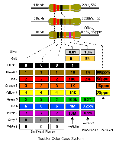
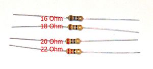
The kit will provide 4 resistors, 22 Ohm, 20 Ohm, 18 Ohm and 16 Ohm. Always start with 22 Ohm, then go to next one if it doesn't work.
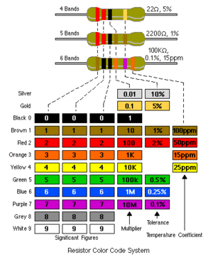
This is how to read the color coded resistors:
OK. Let's get started!
Complete diagram
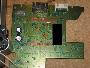
This is the overall diagram of the connections:
The advantage
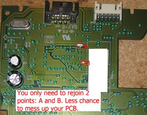
You only need to rejoin 2 points. Other methods involves at least 6 points, not to mention that you need to remove the paints etc.
Remove the Liteon DVD PCB
The first step is to remove the Liteon DVD drive from your xbox 360, if you don't know how to do that, you can google it.
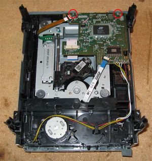
Once you have the DVD drive removed from your XBOX 360, remove the cover and then locate the two screws and remove them:
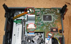
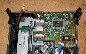
Then unlatch the three flat cables as shown in the pic:
Now you have the cables removed:
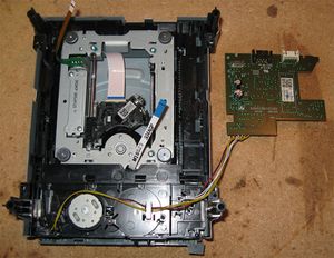
Carefully remove the PCB from the DVD drive housing:
Make two cuts on the PCB
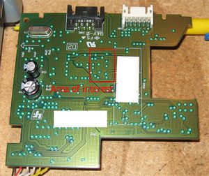
Close up of the PCB:
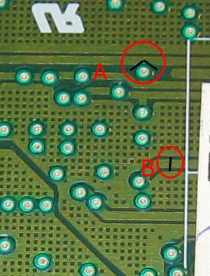
We will be working on the circled area in the above picture. Here is a close up of the AOI.
As you can see from the above picture, we need to make two cuts (A and B).
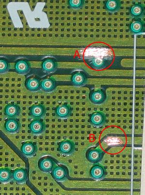
First, use a utility knife, carefully remove the paint above the PCB trace at A and B:
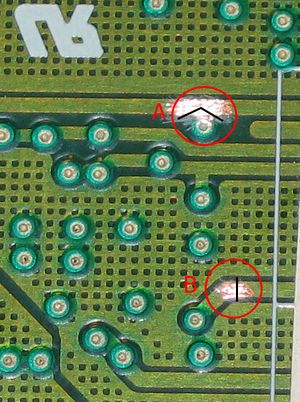
Then, use a sharp utility to make a V cut at point A and straight cut at point B, do NOT cut too deep, and be gentle. You may want to practice before you make the real cut. For point A, it is recommended to make the cut as shown in the pic, in the middle of the trace. The purpose of this cut is to isolate the pad from the 3.3V line and also keep the 3.3V line connected. For point B, just make a straight cut as show in the pic below. Again, be gentle and practice many many times before work on the PCB!!!
OK, the result:
If you have a multimeter, it is recommended to check you have isolated the pad from the 3.3v line and you have broken the trace at point B. If you don't have multimeter, then it is still ok, but you will have to make sure it is done correctly.
Prepare to read
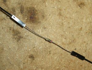
Now, insert one end of the 22 Ohm resistor to the black flexible cable's header and the other end to the 20cm flexible cable. We will start with 22 Ohm resistor, if it doesn't work, try 20 Ohm, if it still doesn't work, try 18 Ohm, and then 16 Ohm.
This is how to read color coded resistors:
Check with the following photo to identify the resistors comes with the package:
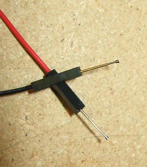
Insert pogo pins to RED flexible cable and the other end of the 20CM flexible cable:
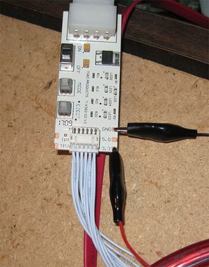
Now, connect our DVD adapter to your PC's Molex adapter, using DVD power cable to connect your Liteon PCB with DVD power adapter, and connect your PC's SATA port to Liteon's SATA port. Then attach the red alligator to the 3.3v pad and the black alligator to GND pad on our DVD power adapter. Make sure you are firmly connected all the cables or alligator clips.
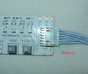
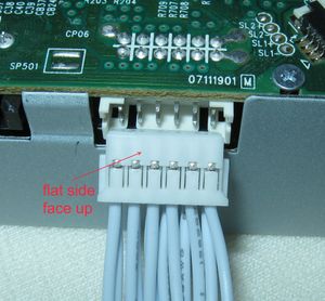
Attention: Make sure you connect the DVD power cable to the DVD adapter and DVD drive in the correct direction. One side of the DVD cable's header has a raised bar, another side is flat, make you connect them in the correct way as show in the picture below:
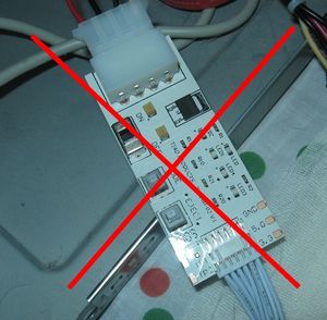
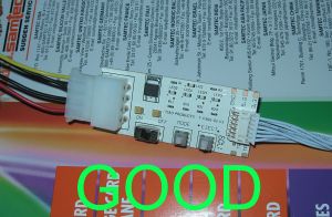
Attention: Do not let the DVD adapter to touch any metal object or your PC's case. Always put a book under the DVD adapter to prevent short circuit:
Alligator clips attached:
Read the key
In this step, we will need to run dosflash or jungleflasher to read the key.
Before we do anything, let's get familiar with the points we will be working on.
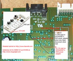
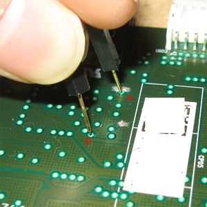
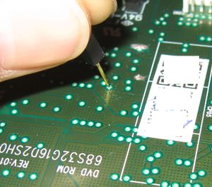
We will need to apply 3.3v to the bottom pad as shown in the pic while we are reading the key, and we will need to connect the top pad via a resistor (22/20/18/16) to GND to get the DVD driver recognized by DOSFLASH or Jungleflasher, once the driver is recognized, we will need to disconnect top via from GND while we are reading the key.
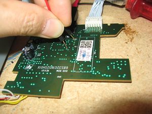
Now, use your left hand to hold the pogo pin (connect to 3.3V via RED cable) on the bottom via (B), use your right hand to hold the pogo pin (connect to the resistor then to GND via BLACK cable) on the top via (A), then slowly hand over the black header to your left hand, so you can free up your right hand. Try to use you left hand to release the BLACK header (on point A) while keeping the B connected to 3.3V. Practice a few times, until you are ok. Make sure pogo pin on black header do NOT touch anything after it is disconnected from point A.
OK. are you ready?
Make sure DVD power adapter is OFF, turn on PC, open windows explore to location Dosflash 1.8, make sure it is highlighted so with a single hit of Enter button, you will have it launched. The reason for that is, your left hand is busy holding the pogo pin, so you only have one hand to use :-) Also make sure you have easy access to your mouse, because you need to click 'Ready' button in Dosflash.
Double check the trace again, make sure they are cut, and DVD power cable is connected in the right direction. If everything is ok, use your left hand to hold the pogo pins to B (to 3.3V) and A (to GND via a resistor) as shown in above pic, then turn on the DVD power adapter:
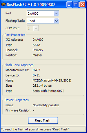
Launch DOSFlash, you will see status is 0x72:
Once the status is 0x72, you can read the key... but before you ready the firmware, you will need to disconnect the pogo pin from point A (black one, connect to GND via resistor), but make sure you still keep point B connected to 3.3V:
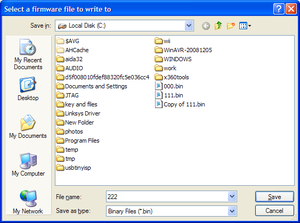
Now you click 'Read Flash' button on Dosflash, it will pop up a dialog box, you select the path and file name of the firmware:
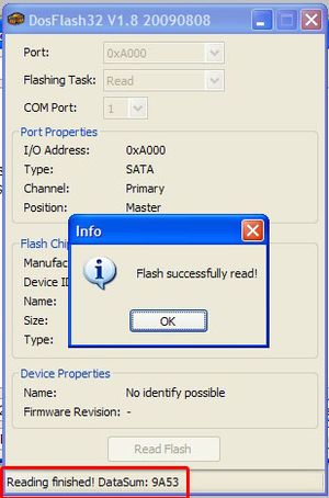
Flash is read:
Now, power off the DVD power adapter, read again, and save to a different file, after that compare it with the first dump, make sure they are identical. (this is to verify the dump is good).
Rejoin the PCB cuts
OK. You have made two cuts to the PCB, it's time to rejoin them back.
In this step, you will need to use the silver conductive glue (included in your purchase) to rejoin the traces.
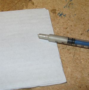
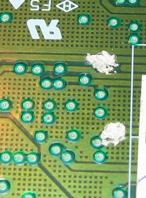
Use a small flat head screw driver, dip s tiny amount (size of sesame) of the silver conductive glue and put it on the trace, DO NOT use the needle attached on the syringe. DO not put a large amount other then the width of the trace:
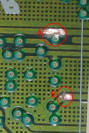
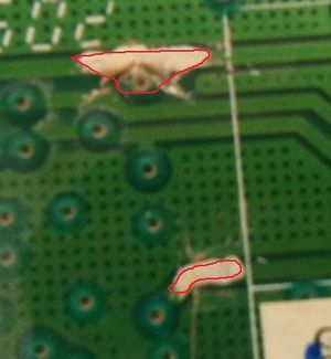
This is a better picture, fill in the red-circled area, do not cross the red circle.
In the above picture, I messed a bit, don't worry, you can fix it.
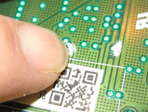
Use your small flat head screw driver to push the redundant glue onto the trace and press it make it firm. You can also use your finger nail to do that, the key is be gentle. The guideline is to have the glue cover all the areas without paint, and the thickness is about 0.2mm.
After you have done that, let it try for a couple hours, then use a multimeter to check the joints, make sure they are solid and correct. This is very important.
If everything is ok, put the PCB back to the housing and your are done with hardware part.
Manually spoof the firmware
You need to download the ixtreme 1.6 templates for liteon, google it for download.
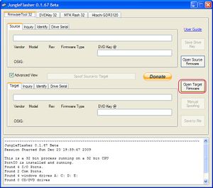
Launch Jungleflasher 1.67b or higher, click on the 'Open Target Firmware':
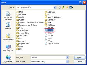
In the popup, select the firmware you dumped from your liteon DVD drive, in my example, it is 111.bin:
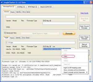
Dumped firmware loaded, you can see the key is found. Highlight the key field, right mouse button click and select "Copy" to copy the key to your clipboard:
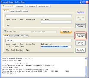
Click 'Open target firmware' again, this time select the ixtreme firmware template for your particular version of DVD drive:
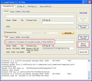
Once you have the template firmware loaded, click 'Manual spoofing' button:
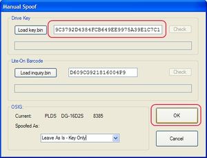
Now, highlight the key field, delete the key and then paste your key (copied from the previous step) to the key field, then click OK:
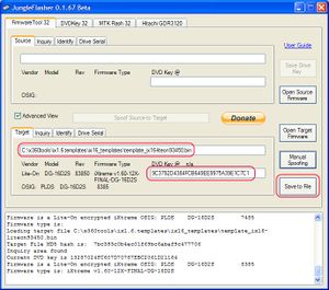
Now the firmware is spoofed with your own key, double check the key is your key. click 'Save to file' button:
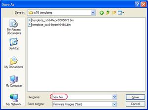
In the dialog box, type in the file name and location of your spoofed firmware:
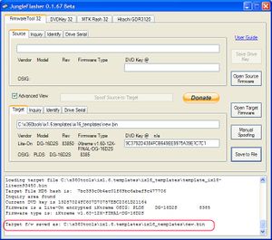
After you press 'Save', you will be back to the main window, check the status box, you will see your firmware is correctly saved:
Now you have finished this step. The next step is to erase the firmware and write the new firmware to your liteon. You can follow our tutorials:
- Flash XBOX 360 Lite-on DVD drive with spoofed firmware
- Extracting key, spoofing firmware and flashing XBOX 360 Lite-on DVD drive using JungleFlasher in Windows (No PC Freezing)
Troubleshooting
If you got status 0x80, 0x52 or 0x51, turn off your dvd power adapter for 5 seconds and turn on again, it may change to 0x72.
If the above does not work, try to replace the resistor to a lower value, e.g from 22to 20, or from 20 to 18, from 18 to 16 and try again. Do not go below 16.
If your PC freezes when you turn on your DVD power adapter, you can do it in DOS (use DOSFLASH 16bit version in DOS), or change your SATA driver to UNIATA driver as mentioned in the following tutorial and the do it again:
Buy Game Console Adapters from http://www.easymg.com or http://www.diygadget.com

10 PCS, 10cm x 10cm, 2 layers prototype for $38.80 shipped!

