TIAO GBoard/GIMX Board Hardware Layout
From TIAO's Wiki

10 PCS, 10cm x 10cm, 2 layers prototype for $38.80 shipped!
Contents
TIAO GBoard / GIMX Adapter
For system connection diagram as GIMX adapter, please refer to TIAO GIMX System Connection Diagram.
The TIAO GBoard / GIMX adapter is a combined all in one board for serial and AVR development. It also provides jumper connections for easy and quick GIMX connectoion (to be used as a GIMX Game Input MultipleXer or Game Input MatriX adapter. For more information on GIMX, please check it out here.
The TIAO GBoard/GIMX Adapter features:
- All in one board contains USB to COM adapter and ATMEVA32U4 for AVR development.
- Bootloader is installed on the ATMEGA32U4, so you don't need a programmer to load the firmware.
- Quick connection jumpers to convert the GBoard to a GIMX adapter
- RX/TX LED, enable LEDs or use the pins for IO ports
TIAO GBoard/GIMX Adapter Hardware Dimensions
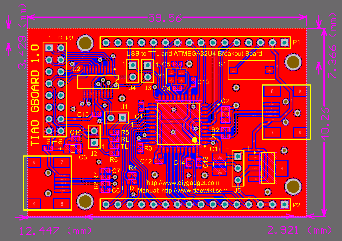
The board dimension of TSS is 59.56 x 40.26mm. It also has 4 mounting holes, the radius of the mounting hole is 2.5mm:
TIAO GBoard/GIMX Adapter Connector Layouts
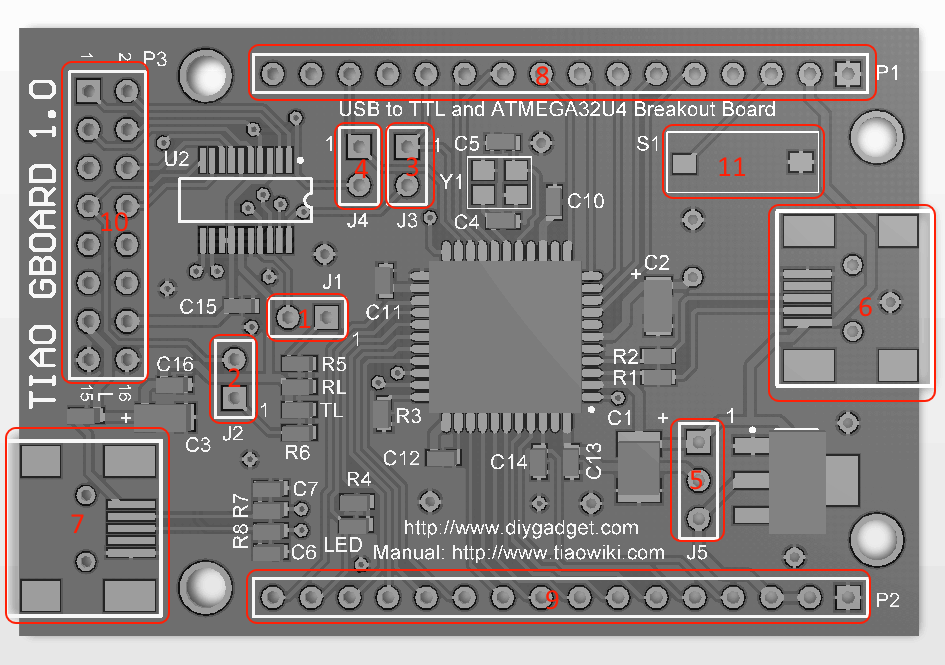
The following picture shows the connector layout of the TIAO GBoard/GIMX Adapter.
- USB to COM RX LED
- USB to COM TX LED
- GIMX TXD Enable
- GIMX RXD Enable
- ATMEGA32U4 Power Select
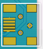
- ATMEGA32U4 USB Connector
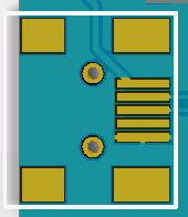
- FT231X USB Connector
- ATMEGA32U4 IO Pin Header 1
- ATMEGA32U4 IO Pin Header 2
- FT231X IO Pin Header
- ATMEGA32U4 Bootloader Pin
J1
- Jumper on: Enable RX Led for USB to COM/Serial.
- Jumper off: Enable CBUS1 output for FT231X.
J2
- Jumper on: Enable TX Led for USB to COM/Serial.
- Jumper off: Enable CBUS2 output for FT231X.
J3
- Jumper on: Enable board to be a DIY GIMX adapter (J4 has to be on as well)
- Jumper off: Enable board to be a AVR and USB to Serial development board. (J4 has to be off as well)
J4
- Jumper on: Enable board to be a DIY GIMX adapter (J3 has to be on as well)
- Jumper off: Enable board to be a AVR and USB to Serial development board. (J3 has to be off as well)
J5
- Jumper on 1-2: Enable 3.3V IO on ATMEGA32U4.
- Jumper on 2-3: Enable 5.0V IO on ATMEGA32U4.
ATMEGA32U4 USB Connector
- The USB connector for ATMEGA32U4.
FT232X USB Connector
- The USB connector for FT231X.
ATMEGA32U4 IO Pin Header 1
| Pin # | ATMEGA32U4 Pin |
|---|---|
| 1 | GND |
| 2 | +5V |
| 3 | RST (Low) |
| 4 | PE6 |
| 5 | PB0 |
| 6 | PB1 |
| 7 | PB2 |
| 8 | PB3 |
| 9 | PB7 |
| 10 | PD0 |
| 11 | PD1 |
| 12 | PD2 |
| 13 | PD5 |
| 14 | PD3 |
| 15 | PC6 |
| 16 | PC7 |
ATMEGA32U4 IO Pin Header 2
| Pin # | ATMEGA32U4 Pin |
|---|---|
| 1 | GND |
| 2 | Vcc (5.0 or 3.3 depending on J5) |
| 3 | Vcc (5.0 or 3.3 depending on J5) |
| 4 | AREF |
| 5 | PF0 |
| 6 | PF1 |
| 7 | PF4 |
| 8 | PF5 |
| 9 | PF6 |
| 10 | PF7 |
| 11 | PB6 |
| 12 | PB5 |
| 13 | PB4 |
| 14 | PD7 |
| 15 | PD6 |
| 16 | PD4 |
FT231X IO Pin Header
| Pin # | FT231X Pin |
|---|---|
| 1 | RTS |
| 2 | DTR |
| 3 | RI |
| 4 | RXD |
| 5 | DSR |
| 6 | DCD |
| 7 | TXLED/CBUS2 |
| 8 | CTS |
| 9 | RXLED/CBUS1 |
| 10 | CBUS0 |
| 11 | CBUS3 |
| 12 | TXD |
| 13 | V5 |
| 14 | V33 |
| 15 | GND |
| 16 | GND |
ATMEGA32U4 Bootloader Pin
- ATMEGA32U4 Bootloader Pin, press and hold to enter bootloader mode.

10 PCS, 10cm x 10cm, 2 layers prototype for $38.80 shipped!


