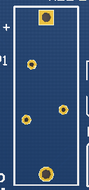
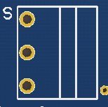
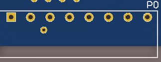
Difference between revisions of "TIAO Smart Network Sprinkler Controller Hardware Layout"

10 PCS, 10cm x 10cm, 2 layers prototype for $38.80 shipped!
(→TSS Connector Layouts) |
|||
| (14 intermediate revisions by the same user not shown) | |||
| Line 6: | Line 6: | ||
For system connection diagram, please refer to [[TIAO Smart Network Sprinkler Controller System Connection Diagram]]. | For system connection diagram, please refer to [[TIAO Smart Network Sprinkler Controller System Connection Diagram]]. | ||
| − | The [ | + | The [https://www.diygadget.com/lawn-sprinkler-controller-and-accessories/155-tiao-smart-network-sprinkler-controller-16-station-sprinkler-controller-open-source-desktop-mobile-app.html TIAO Smart Network Sprinkler Controller (TSS)] is a piece of hardware controls your irrigation systems. It replaces your traditional sprinkler controller. [https://www.diygadget.com/lawn-sprinkler-controller-and-accessories/155-tiao-smart-network-sprinkler-controller-16-station-sprinkler-controller-open-source-desktop-mobile-app.html TSS] has many benefits over the traditional sprinkler controller: |
* Web interface - program the watering schedule using your PC or mobile phone | * Web interface - program the watering schedule using your PC or mobile phone | ||
| Line 41: | Line 41: | ||
# [[#USB B|USB B - for updating firmware]] | # [[#USB B|USB B - for updating firmware]] | ||
# [[#RF Header|RF Header - Radio Frequency (RF) transmitter Header]] | # [[#RF Header|RF Header - Radio Frequency (RF) transmitter Header]] | ||
| − | # [[#ISP | + | # [[#ISP header|ISP header]] |
# [[#Extension board header|Extension board header - connect extension boards]] | # [[#Extension board header|Extension board header - connect extension boards]] | ||
| − | # [[#MicroSD socket | + | # [[#MicroSD socket|MicroSD socket - optional]] |
# [[#AVR Power selector|AVR Power selector - AVR power voltage selector]] | # [[#AVR Power selector|AVR Power selector - AVR power voltage selector]] | ||
| − | + | # [[#Relay header|Relay header]] | |
| − | # [[#Relay | + | # [[#Soft button 1|Button 1]] |
| − | # [[# | + | # [[#Soft button 2|Button 2]] |
| − | # [[# | + | # [[#Soft button 3|Button 3]] |
| − | # [[# | + | # [[#LCD display header|LCD display header]] |
| − | # [[# | + | # [[#Ethernet receptacle|Ethernet receptacle]] |
| − | # [[# | + | # [[#Fuse holder|Fuse holder holds the 2A fuse]] |
| − | # [[# | + | # [[#Power switch|Power switch]] |
| − | # [[# | + | # [[#Power status LED|Power Status LED]] |
| − | # [[# | ||
| − | |||
# [[#24V AC and rain sensor header|AC In, Common wire and rain sensor connector]] | # [[#24V AC and rain sensor header|AC In, Common wire and rain sensor connector]] | ||
# [[#Station 1-16 header|Connect to each individual valve]] | # [[#Station 1-16 header|Connect to each individual valve]] | ||
| − | |||
==== Pin Out ==== | ==== Pin Out ==== | ||
| Line 170: | Line 167: | ||
==== Extension board header ==== | ==== Extension board header ==== | ||
| − | [[Image:tss- | + | [[Image:tss-Ext.png||None]] |
{| | {| | ||
| Line 204: | Line 201: | ||
==== MicroSD socket ==== | ==== MicroSD socket ==== | ||
| − | + | [[Image:Tss-MicroSD.png||None]] | |
Optional MicroSD socket for logging. | Optional MicroSD socket for logging. | ||
==== AVR Power selector ==== | ==== AVR Power selector ==== | ||
| + | [[Image:Tss-PJ.png||None]] | ||
Select power source for AVR Microcontroller. Default is 3.3v. | Select power source for AVR Microcontroller. Default is 3.3v. | ||
3.3v Power: jumper over pin 1 and 2. | 3.3v Power: jumper over pin 1 and 2. | ||
| Line 214: | Line 212: | ||
==== Relay header ==== | ==== Relay header ==== | ||
| − | [[Image: | + | [[Image:Tss-Relay.png||None]] |
{| | {| | ||
| Line 230: | Line 228: | ||
|} | |} | ||
| − | The relay is rated as | + | The relay is rated as 250V/3A/AC or 30V/3A/DC, however for safety concerns, please DO NOT connect anything higher than 28V/2A. |
| + | ==== Soft button 1 ==== | ||
| + | [[Image:Tss-B1.png||none]] | ||
| − | + | The function of B1/B2/B3 depends on the firmware version. For version 2.1.4, these are the functions: | |
| − | |||
| − | |||
| − | The | ||
{| | {| | ||
| − | ! align="left"| | + | ! align="left"|Press then release |
| − | ! | + | ! Press and hold |
| − | |||
| − | |||
| − | |||
| − | |||
| − | |||
| − | |||
| − | |||
| − | |||
| − | |||
| − | |||
| − | |||
| − | |||
| − | |||
| − | |||
| − | |||
| − | |||
| − | |||
| − | |||
| − | |||
| − | |||
| − | |||
| − | |||
| − | |||
| − | |||
| − | |||
|- | |- | ||
| − | | | + | | Display current IP address |
| − | | | + | | Stop all stations immediately. |
| − | |||
| − | |||
| − | |||
| − | |||
| − | |||
| − | |||
| − | |||
| − | |||
| − | |||
| − | |||
| − | |||
| − | |||
| − | |||
|} | |} | ||
| + | ==== Soft button 2 ==== | ||
| + | [[Image:Tss-B2.png||none]] | ||
| + | The function of B1/B2/B3 depends on the firmware version. For version 2.1.4, these are the functions: | ||
| − | |||
| − | |||
| − | |||
| − | |||
{| | {| | ||
| − | ! align="left"| | + | ! align="left"|Press then release |
| − | ! | + | ! Press and hold |
|- | |- | ||
| − | | | + | | Display MAC address |
| − | | | + | | Restart controller |
| − | |||
| − | |||
| − | |||
| − | |||
| − | |||
| − | |||
| − | |||
| − | |||
| − | |||
|} | |} | ||
| − | |||
| − | |||
| − | + | ==== Soft button 3 ==== | |
| − | + | [[Image:Tss-B3.png||none]] | |
| − | + | The function of B1/B2/B3 depends on the firmware version. For version 2.1.4, these are the functions: | |
| − | |||
| − | |||
| − | |||
| − | |||
| − | |||
| − | |||
| − | |||
| − | |||
| − | |||
| − | |||
| − | |||
| − | |||
| − | ==== | ||
| − | [[Image: | ||
{| | {| | ||
| − | ! align="left"| | + | ! align="left"|Press then release |
| − | ! | + | ! Press and hold |
|- | |- | ||
| − | | | + | | Toggle between the main controller (MC) and each expansion board (E1, E2, etc). |
| − | + | | Manually start an existing program or a test program. | |
| − | |||
| − | |||
| − | |||
| − | |||
| − | |||
| − | |||
| − | |||
| − | |||
| − | |||
| − | |||
| − | |||
| − | |||
| − | |||
| − | |||
| − | | | ||
|} | |} | ||
| − | |||
| − | |||
| − | |||
| − | |||
| − | |||
| − | |||
| − | |||
| − | |||
| − | |||
| − | |||
| − | |||
| − | |||
| − | |||
| − | |||
| − | |||
| − | |||
| − | |||
| − | |||
| − | |||
| − | |||
| − | |||
| − | |||
| − | |||
| − | |||
| − | |||
| − | |||
| − | |||
| + | ==== LCD display header ==== | ||
| + | [[Image:Tss-LCD.png||none]] | ||
| − | + | Insert the LCD module directly on the LCD header. Make sure pins are aligned, otherwise the LCD/controller will be damaged. | |
| − | |||
| − | |||
| − | + | ==== Ethernet receptacle ==== | |
| − | + | [[Image:Tss-Net.png||none]] | |
| − | + | Plug Ethernet cable here for network access. If wired network is not available, there are many other options, such as using a wireless router in client mode (for example: [http://www.diygadget.com/150mbps-wireless-n-nano-router-micro-usb-power-tl-wr702n.html 150Mbps Wireless N Nano Router (Micro USB Power) TL-WR702N] or [http://www.diygadget.com/150mbps-wireless-n-mini-pocket-router-direct-power-tl-wr700n.html 150Mbps Wireless N Mini Pocket Router (direct power) TL-WR700N]) or powerline network adapter kit ([http://www.diygadget.com/linxe-lsp06-200mbps-etherent-powerline-network-adapter-kit-2.html Linxe LSP06 200Mbps etherent powerline network adapter Kit (2)]). | |
| − | |||
| − | | | ||
| − | | | ||
| − | |||
| − | |||
| − | |||
| − | |||
| − | |||
| − | |||
| − | |||
| − | |||
| − | |||
| − | |||
| − | |||
| − | |||
| − | |||
| − | |||
| − | |||
| − | |||
| − | |||
| − | |||
| − | |||
| − | |||
| − | |||
| − | |||
| − | |||
| − | |||
| − | |||
| − | |||
| − | |||
| − | |||
| − | |||
| − | |||
| − | |||
| − | |||
| − | |||
| − | |||
| − | |||
| − | |||
| − | |||
| − | |||
| − | |||
| − | |||
| − | |||
| − | |||
| − | |||
| − | |||
| − | |||
| − | |||
| − | |||
| − | |||
| − | |||
| − | |||
| − | |||
| − | |||
==== Fuse holder ==== | ==== Fuse holder ==== | ||
| − | [[Image: | + | [[Image:Tss-Fuse.png||None]] |
| − | The | + | The on board fuse hold. The fuse is rated at 2A. |
| + | ==== Power switch ==== | ||
| + | [[Image:Tss-Pwr.png]] | ||
| − | + | The main power switch. Slide up to turn on the controller, slide down to turn off the controller. | |
| − | |||
| − | + | ==== Power status LED ==== | |
| + | [[Image:Tss-PwrLED.png||none]] | ||
| + | Power status LEDs. | ||
{| | {| | ||
| − | ! align="left"| | + | ! align="left"|Pin |
! Description | ! Description | ||
| − | |||
| − | |||
| − | |||
| − | |||
| − | |||
| − | |||
|- | |- | ||
| PWR | | PWR | ||
| − | | ON | + | | ON: VIN (5V) is working |
|- | |- | ||
| − | | | + | | V33 |
| − | | ON | + | | ON: Vcc (3.3V) is working |
|} | |} | ||
| − | |||
==== 24V AC and rain sensor header ==== | ==== 24V AC and rain sensor header ==== | ||
| − | [[Image: | + | [[Image:Tss-Header1.png||None]] |
| − | This header allows you to connect the power (24V, 2A AC) to the | + | This header allows you to connect the power (24V, 2A AC) to the TSS. This is the only power source needed for the controller. |
For power, connect one of the 24V AC 2A transformer's terminal to pin 8 (24V AC In) and the other terminal to pin 7 (GND) | For power, connect one of the 24V AC 2A transformer's terminal to pin 8 (24V AC In) and the other terminal to pin 7 (GND) | ||
For rain sensor, connect one of the rain sensor's terminal to pin 5 (Rain sensor terminal) and the other terminal to pin 6. | For rain sensor, connect one of the rain sensor's terminal to pin 5 (Rain sensor terminal) and the other terminal to pin 6. | ||
| Line 498: | Line 330: | ||
| 24V AC In | | 24V AC In | ||
|} | |} | ||
| − | |||
==== Station 1-16 header ==== | ==== Station 1-16 header ==== | ||
| − | [[Image: | + | [[Image:Tss-Header2.png||None]] |
| − | + | TSS can control 16 stations (including master station if you have one) without expansion board. This header has 16 connectors, so you can connect up to 16 valves. | |
* Example 1: My irrigation system has 10 stations, I do not have a master station. | * Example 1: My irrigation system has 10 stations, I do not have a master station. | ||
| Line 509: | Line 340: | ||
* Example 2: My irrigation system has 15 stations, I have a master station. | * Example 2: My irrigation system has 15 stations, I have a master station. | ||
** Connect RED wires of the valves to 'Common wire' connectors (see [[#24V AC and rain sensor header]]), then connect BLACK wire of the the master valve to connector 16, and other BLACK wires of regular valves to connector 1 to 15 respectively. | ** Connect RED wires of the valves to 'Common wire' connectors (see [[#24V AC and rain sensor header]]), then connect BLACK wire of the the master valve to connector 16, and other BLACK wires of regular valves to connector 1 to 15 respectively. | ||
| − | |||
| − | |||
| − | |||
| − | |||
| − | |||
Latest revision as of 21:15, 3 November 2017
Contents
- 1 TIAO Smart Network Sprinkler Controller
- 1.1 TSS Hardware Dimensions
- 1.2 TSS Connector Layouts
- 1.2.1 Pin Out
- 1.2.2 USB B
- 1.2.3 RF Header
- 1.2.4 ISP header
- 1.2.5 Extension board header
- 1.2.6 MicroSD socket
- 1.2.7 AVR Power selector
- 1.2.8 Relay header
- 1.2.9 Soft button 1
- 1.2.10 Soft button 2
- 1.2.11 Soft button 3
- 1.2.12 LCD display header
- 1.2.13 Ethernet receptacle
- 1.2.14 Fuse holder
- 1.2.15 Power switch
- 1.2.16 Power status LED
- 1.2.17 24V AC and rain sensor header
- 1.2.18 Station 1-16 header
TIAO Smart Network Sprinkler Controller
For system connection diagram, please refer to TIAO Smart Network Sprinkler Controller System Connection Diagram.
The TIAO Smart Network Sprinkler Controller (TSS) is a piece of hardware controls your irrigation systems. It replaces your traditional sprinkler controller. TSS has many benefits over the traditional sprinkler controller:
- Web interface - program the watering schedule using your PC or mobile phone
- Supports complicate watering schedules
- Unlimited watering schedules
- Allow seasonal adjustments
- Weather API access - automatically adjust watering amount/time by checking online weather forecast (rain/wind etc)
- Control your sprinkler stations from anywhere in the world
- Software supports unlimited stations
- Total of 16 stations (or 1 master station + 15 stations), can expend to unlimited stations using our extension board
- Software supports unlimited stations
- Supports rain sensor
- Open source software - which means you can add your own function to the controller!
- System ON/OFF hardware switch
- Status LEDs (5V and 3.3v power)
- Status LCD - displays system status etc
- Low cost! It's cheaper than the traditional sprinkler controller!
TSS Hardware Dimensions
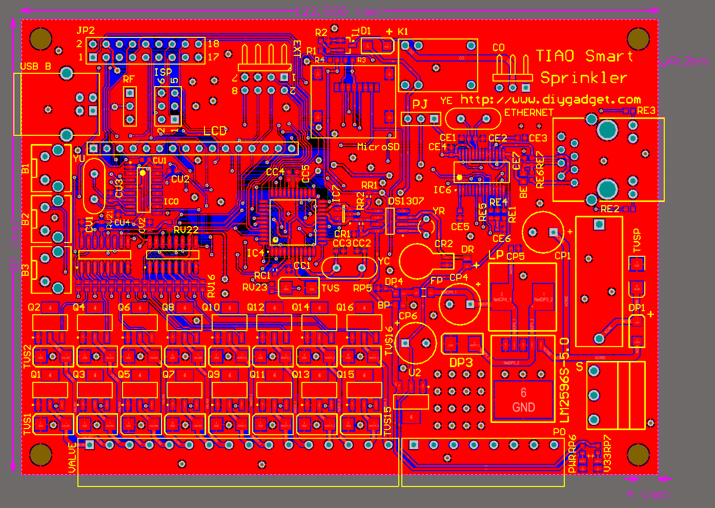
The board dimension of TSS is 122.5 x 87mm, or 48.2 x 34.2 inch. It also has 4 mounting holes, the radius of the mounting hole is 2mm:
TSS Connector Layouts
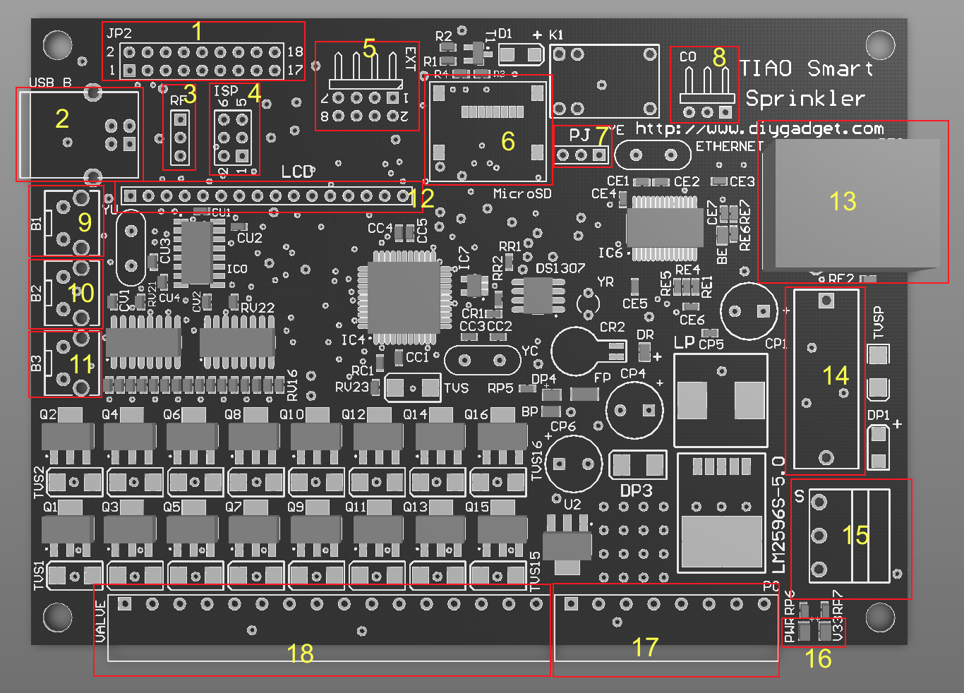
The following picture shows the connector layout of the TSS. You plug the LCD module directly on top of TSS without using any wires.
- Pin Out - for testing purpose
- USB B - for updating firmware
- RF Header - Radio Frequency (RF) transmitter Header
- ISP header
- Extension board header - connect extension boards
- MicroSD socket - optional
- AVR Power selector - AVR power voltage selector
- Relay header
- Button 1
- Button 2
- Button 3
- LCD display header
- Ethernet receptacle
- Fuse holder holds the 2A fuse
- Power switch
- Power Status LED
- AC In, Common wire and rain sensor connector
- Connect to each individual valve
Pin Out
| Pin # | Description |
|---|---|
| 1 | SDA |
| 2 | GND |
| 3 | SCL |
| 4 | V5 |
| 5 | ADC5 |
| 6 | V3.3 |
| 7 | ADC7 |
| 8 | ADC6 |
| 9 | TXD |
| 10 | RXD |
| 11 | SCK |
| 12 | PD2 |
| 13 | MISO |
| 14 | MOSI |
| 15 | V3.3 |
| 16 | AIN0 |
| 17 | GND |
| 18 | PD7 |
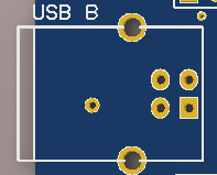
USB B
Connect this USB port to PC or laptop (USB A male to USB B female) to update TSS firmware.
RF Header
| Pin # | Description |
|---|---|
| 1 | A3 - Data |
| 2 | VIN - 5V |
| 3 | GND |
Radio Frequency (RF) transmitter header. Works with standard 434MHz or 315MHz RF transmitter.
ISP header
| Pin # | Description |
|---|---|
| 1 | MISO |
| 2 | VIN - 5V |
| 3 | SCK |
| 4 | MOSI |
| 5 | RESET |
| 6 | GND |
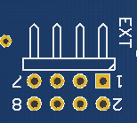
Extension board header
| Pin # | Description |
|---|---|
| 1 | Vcc - 3.3V |
| 2 | QH* |
| 3 | A4/ADC4 |
| 4 | Clock/TOSC1 |
| 5 | GND |
| 6 | Latch/AIN1 |
| 7 | GND |
| 8 | OE/T1 |
Connect any extension boards to this header.
MicroSD socket
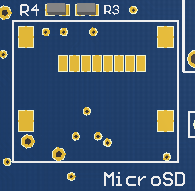 Optional MicroSD socket for logging.
AVR Power selector
 Select power source for AVR Microcontroller. Default is 3.3v.
3.3v Power: jumper over pin 1 and 2.
5V power: jumper over pin 2 and 3.
Relay header
| Pin # | Description |
|---|---|
| 1 | NC - Normally closed pin |
| 2 | CO - Change over pin |
| 3 | NO - Normally open pin |
The relay is rated as 250V/3A/AC or 30V/3A/DC, however for safety concerns, please DO NOT connect anything higher than 28V/2A.
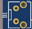
Soft button 1
The function of B1/B2/B3 depends on the firmware version. For version 2.1.4, these are the functions:
| Press then release | Press and hold |
|---|---|
| Display current IP address | Stop all stations immediately. |
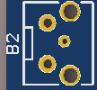
Soft button 2
The function of B1/B2/B3 depends on the firmware version. For version 2.1.4, these are the functions:
| Press then release | Press and hold |
|---|---|
| Display MAC address | Restart controller |
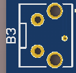
Soft button 3
The function of B1/B2/B3 depends on the firmware version. For version 2.1.4, these are the functions:
| Press then release | Press and hold |
|---|---|
| Toggle between the main controller (MC) and each expansion board (E1, E2, etc). | Manually start an existing program or a test program. |
LCD display header
Insert the LCD module directly on the LCD header. Make sure pins are aligned, otherwise the LCD/controller will be damaged.
Ethernet receptacle
Plug Ethernet cable here for network access. If wired network is not available, there are many other options, such as using a wireless router in client mode (for example: 150Mbps Wireless N Nano Router (Micro USB Power) TL-WR702N or 150Mbps Wireless N Mini Pocket Router (direct power) TL-WR700N) or powerline network adapter kit (Linxe LSP06 200Mbps etherent powerline network adapter Kit (2)).
Fuse holder
The on board fuse hold. The fuse is rated at 2A.
Power switch
The main power switch. Slide up to turn on the controller, slide down to turn off the controller.
Power status LED
Power status LEDs.
| Pin | Description |
|---|---|
| PWR | ON: VIN (5V) is working |
| V33 | ON: Vcc (3.3V) is working |
24V AC and rain sensor header
This header allows you to connect the power (24V, 2A AC) to the TSS. This is the only power source needed for the controller. For power, connect one of the 24V AC 2A transformer's terminal to pin 8 (24V AC In) and the other terminal to pin 7 (GND) For rain sensor, connect one of the rain sensor's terminal to pin 5 (Rain sensor terminal) and the other terminal to pin 6. The rain sensor is optional.
| Pin | Description |
|---|---|
| 1, 2, 3, 4 | Common wire, connect to sprinkler valve's common terminals. |
| 5 | Rain sensor terminal |
| 6, 7 | GND |
| 8 | 24V AC In |
Station 1-16 header
TSS can control 16 stations (including master station if you have one) without expansion board. This header has 16 connectors, so you can connect up to 16 valves.
- Example 1: My irrigation system has 10 stations, I do not have a master station.
- Connect RED wires of the valves to 'Common wire' connectors (see #24V AC and rain sensor header), then connect BLACK wires of the valves to connector 1 to 10 respectively.
- Example 2: My irrigation system has 15 stations, I have a master station.
- Connect RED wires of the valves to 'Common wire' connectors (see #24V AC and rain sensor header), then connect BLACK wire of the the master valve to connector 16, and other BLACK wires of regular valves to connector 1 to 15 respectively.

10 PCS, 10cm x 10cm, 2 layers prototype for $38.80 shipped!
