Difference between revisions of "TIAO Raspberry Pi Zero Buddy Manual"

10 PCS, 10cm x 10cm, 2 layers prototype for $38.80 shipped!
(Created page with "<meta name="keywords" content="TIAOWIKI,youpcb.com, low price, pcb, prototype"></meta> <meta name="description" content="TIAOWIKI tutorials on how to export gerber files for p...") |
|||
| (2 intermediate revisions by the same user not shown) | |||
| Line 16: | Line 16: | ||
[[Image:Zeroboard.png||none]] | [[Image:Zeroboard.png||none]] | ||
| + | |||
| + | # USB uplink 1 (Can only use uplink 1 or 2, but cannot use both) | ||
| + | # USB downlink 1 | ||
| + | # USB downlink 2 | ||
| + | # USB downlink 3 | ||
| + | # Ethernet RJ45 receptacle for wired internet connection | ||
| + | # USB uplink 2 (Can only use uplink 1 or 2, but cannot use both) | ||
| + | # USB Power selection. Jumper on 1-2: power from uplink 2. Jumper on 2-3: power from uplink 1 | ||
| + | |||
| + | === Up link selection === | ||
| + | This board can be used with a raspberry Pi zero to expand Pi zero to have 3 more USB port and a wired network connection. It can also be used as a USB hub with wired network connection. | ||
| + | |||
| + | If you plan to use it together with Raspberry Pi Zero, it is recommended to use the include cable to make the connection. The supplied cable is a special custom made cable. One end connect to the | ||
| + | micro usb port of the Raspberry Pi Zero, the other end connect to the header #5 on the board. The pinout for the header is: | ||
| + | |||
| + | # (square pad) Vin (5v) | ||
| + | # USB D- | ||
| + | # USB D+ | ||
| + | # GND | ||
| + | # GND | ||
| + | |||
| + | The supplied cable only has 4 wires, so the missing one towards to the upside of the board as shown below: | ||
| + | |||
| + | [[Image:zero2.png||none]] | ||
| + | |||
| + | If you would like to use the ZERO Buddy as a standalone 3 port USB hub with a wired ethernet port then make these adjustments to the Buddy. | ||
| + | |||
| + | # On power header 7, move the jumper to pins 2-3 | ||
| + | # Change the USB uplink from header 6 (J2) to uplink 1 (seen board layout above). | ||
| + | |||
| + | This is achieved by removing the supplied cable from the Buddy header 6 (J2). Then run a | ||
| + | customer supplied USB A to A cable between the Buddy connector uplink 1 to a host computer(PC) USB port. | ||
| + | |||
| + | To make the Buddy a powered USB hub (with or without a PI Zero) make the following adjustments. | ||
| + | |||
| + | # Remove the jumper from header 7 | ||
| + | # Solder a +5V wire to ping 2 of header 7 and a GND wire to the ground pad under the ethernet port 5. | ||
| + | # If there is a Pi Zero attached to the Buddy, via the provided cable, you may want to isolate the Pi ZERO +5V power from the Buddy +5V power. To do this, remove pin 1 from header 6 of the provided cable (red wire; +5V). | ||
Latest revision as of 13:13, 15 July 2016
Buy Game Console Adapters from http://www.easymg.com or http://www.diygadget.com
TIAO Raspberry Pi Zero Buddy User Manual
This manual helps you to connect Raspberry Pi Zero to TIAO Raspberry Pi Zero Buddy purchased from http://www.diygadget.com.
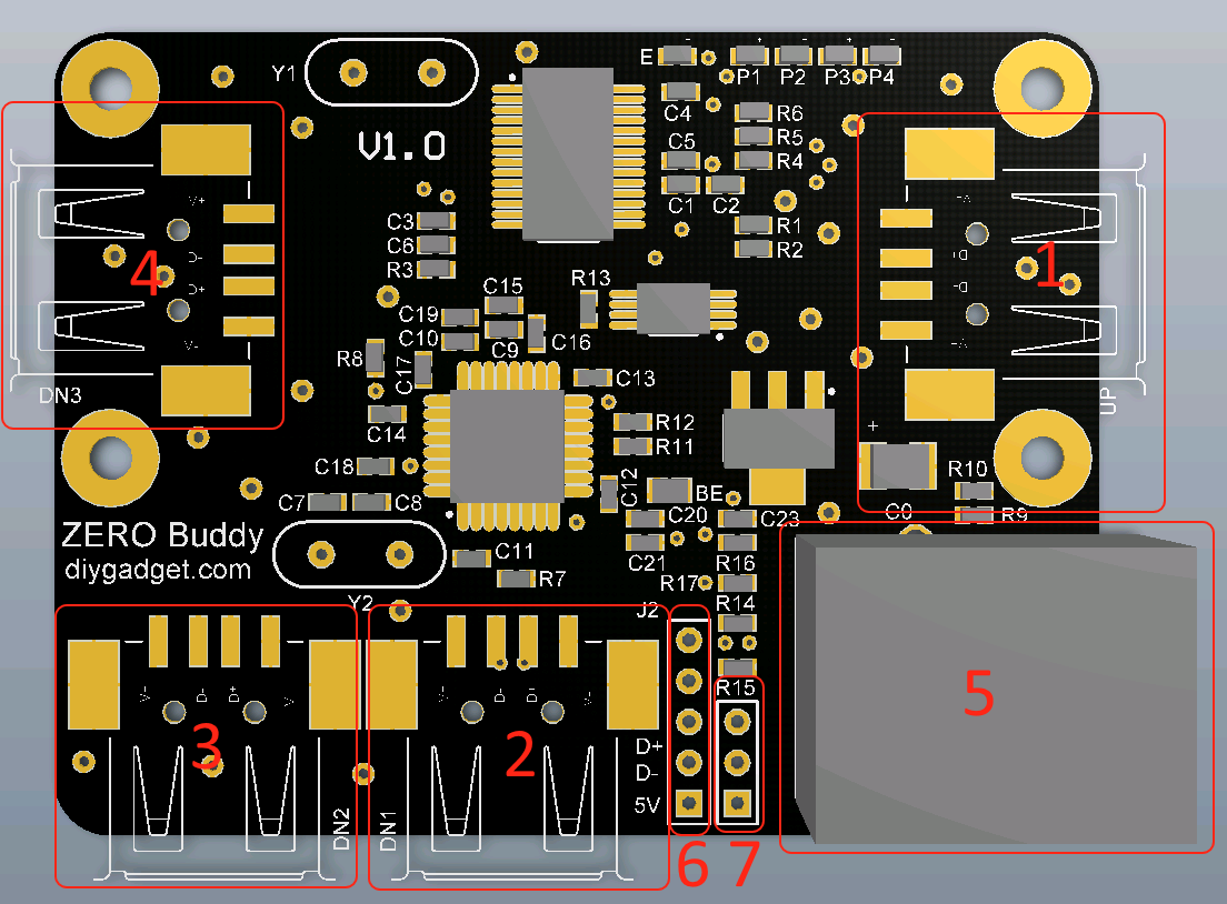
This is the board layout:
- USB uplink 1 (Can only use uplink 1 or 2, but cannot use both)
- USB downlink 1
- USB downlink 2
- USB downlink 3
- Ethernet RJ45 receptacle for wired internet connection
- USB uplink 2 (Can only use uplink 1 or 2, but cannot use both)
- USB Power selection. Jumper on 1-2: power from uplink 2. Jumper on 2-3: power from uplink 1
Up link selection
This board can be used with a raspberry Pi zero to expand Pi zero to have 3 more USB port and a wired network connection. It can also be used as a USB hub with wired network connection.
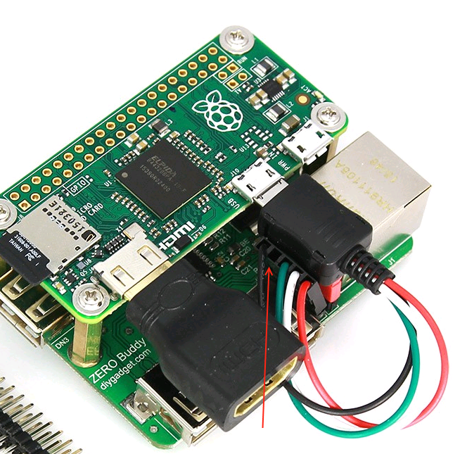
If you plan to use it together with Raspberry Pi Zero, it is recommended to use the include cable to make the connection. The supplied cable is a special custom made cable. One end connect to the micro usb port of the Raspberry Pi Zero, the other end connect to the header #5 on the board. The pinout for the header is:
- (square pad) Vin (5v)
- USB D-
- USB D+
- GND
- GND
The supplied cable only has 4 wires, so the missing one towards to the upside of the board as shown below:
If you would like to use the ZERO Buddy as a standalone 3 port USB hub with a wired ethernet port then make these adjustments to the Buddy.
- On power header 7, move the jumper to pins 2-3
- Change the USB uplink from header 6 (J2) to uplink 1 (seen board layout above).
This is achieved by removing the supplied cable from the Buddy header 6 (J2). Then run a customer supplied USB A to A cable between the Buddy connector uplink 1 to a host computer(PC) USB port.
To make the Buddy a powered USB hub (with or without a PI Zero) make the following adjustments.
- Remove the jumper from header 7
- Solder a +5V wire to ping 2 of header 7 and a GND wire to the ground pad under the ethernet port 5.
- If there is a Pi Zero attached to the Buddy, via the provided cable, you may want to isolate the Pi ZERO +5V power from the Buddy +5V power. To do this, remove pin 1 from header 6 of the provided cable (red wire; +5V).

10 PCS, 10cm x 10cm, 2 layers prototype for $38.80 shipped!

